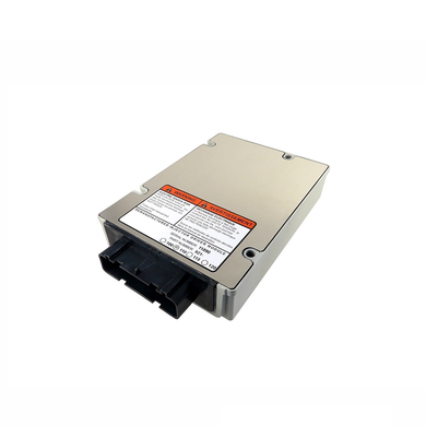

There should be one or two big connectors along the way, take them apart too and check for corrosion. Follow the harness as best as possible under the truck and see if it rubbed through anywhere. Just check for any corrosion or loose wire terminals in the fuse block. There should be a couple of fuses in there. See if you can find the harness at the batteries. The IDM should have a 15 amp fuse in the battery box area. The relay gets it battery power directly from the batteries by a separate ECM/IDM power harness. The relay should also be near the IDM itself at the firewall there. Could be weak voltage supply to the IDM and or corroded wiring. Sounds like the IDM is partially working, but not properly firing the injectors. If the IDM is loosing power and shuts down there are other codes that get logged in the ECM for loss of signal and other communication break downs with the IDM. This alone does not cause the engine to quit.
#7.3 injector driver module relay code#
The actual code is just saying the ecm cannot get the idm to communicate fault codes. The injector drive module is located above the engine on the firewall, the ecm is located kinda above where the clutch pedal is on the inside of the firewall and has a big connector that connects to it through the firewall at the left side near the fender. This code is set when the main ecm cannot communicate with the IDM, (injector drive module). Fuse box diagram (location and assignment of electrical fuses and relays) for Ford F-series Super Duty (F250 / F350 / F450 / F550) (2000, 2001, 2002, 2003). The 543 is a code that will cause the Check Engine light to come on and engine may not run. Soldering: after getting these pieces we have mounted all the required components over the PCB, and connected it with Arduino for demonstration.The 244 code problem is between engine and trans and will not cause the engine to quit.

They are fabricating the PCB at very low rate which $2.Īfter few days of ordering PCB’s I got the PCB samples And you may go with your local PCB vendors too with Gerber output of PCB layout. After you have selected all of the options, click “Save to Cart” and complete your order, then you will get your PCBs a few days later. Here you can select the number of PCBs you want to order, how many copper layers you need, the PCB thickness, copper weight, and even the PCB color.
#7.3 injector driver module relay download#
Then you will access the page PCB order to download Gerber files of your PCB and send them to any manufacturer, it’s also a lot easier (and cheaper) to order it directly in EasyEDA. You can also view the PCB, how it will look after fabrication using the Photo View button in EasyEDA:Īfter completing the design of PCB, you can click the icon of Fabrication output above. While designing your circuits and PCBs, you can also make your circuit and PCB designs public so that other users can copy or edit them and can take benefit from there, we have also made our whole Circuit and PCB layouts public for this Relay Driver Module, check the below link:īelow is the Snapshot of Top layer of PCB layout from EasyEDA, you can view any Layer (Top, Bottom, Topsilk, bottomsilk etc) of the PCB by selecting the layer form the ‘Layers’ Window. They also offer component sourcing service where they have a large stock of electronic components and users can order their required components along with the PCB order. We have previously used EasyEDA many times and found it very convenient to use compared to other PCB fabricators. After designing the PCB, we can order the PCB samples by their low cost PCB fabrication services. To design this Relay Driver Circuit, we have chosen the online EDA tool called EasyEDA. We have connected 220VAC bulb at the terminal block of the PCB board and AC supply is also applied to the board.īelow is the Arduino Code which we have used to demonstrate this Relay module:Īlso check the Video at the end of this article. All four relays are connected with Arduino at 8,9,10 and 11th pins (In1, In2, In3, and In4), and 1 12v adapter is used for powering the circuit. For demonstrating the working of this Relay Module, we have used an Arduino Uno board for controlling relays.


 0 kommentar(er)
